

Maximizing solar energy output is a typical motivation for solar energy investments. Aurora Solar, a market leader in solar design and performance analysis software, has published an in-depth look at the most common reasons for energy loss in PV systems and recommendations for mitigating those losses.
According to the 2022 Solar Generation Index published by KWh Analytics, a climate insurance and renewable energy risk management organisation, solar assets are often performing below expectations. There is a 7–15 percentage point underperformance across the board for systems installed after 2015, albeit this varies somewhat by area. Can this poor performance be prevented, and how?
Basic solar performance ideas, such as the impact of tilt, orientation, and shading on output metrics, are covered in Aurora Solar’s Ultimate Guide to PV System Losses. The impacts of incidence angle modifiers, as well as module nameplate rating losses, are discussed, as are the consequences of using incompatible equipment.
Orientation and slant
The quantity of solar irradiation that a system gets over the course of a year is affected by the angle of the panels. The Aurora study states that the array’s production may be increased by tilting it towards the equator, where incident irradiance will be maximised.
Optimizing the sun incidence angle is also crucial for output. The angle at which the surface of the panel faces the sun is known as its incidence angle. The amount of sunlight that penetrates the front glass of the panel is affected by the incident angle.
According to Aurora, the usual range for these losses, as determined by the incidence angle modifier, is between 3% and 4.5%. The DeSoto model is applied to comprehend the moderating effects of the incidence angle.
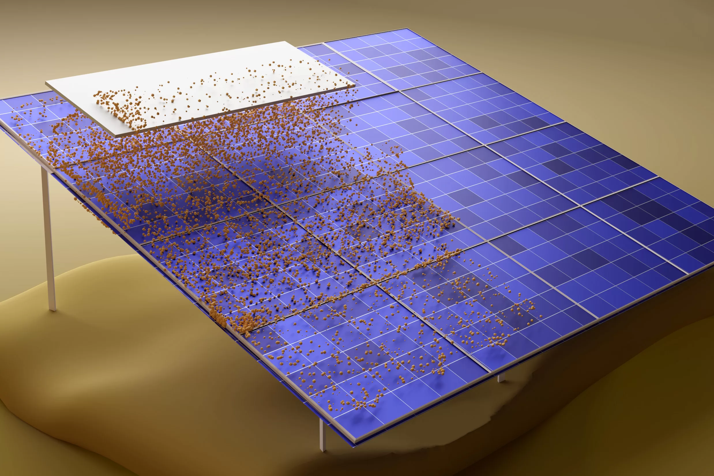
This is because soiling, or the accumulation of dust and other material on the panel’s surface, is a major contributor to energy loss in particular areas. It can result in losses of up to 5% in regions that experience protracted dry seasons. The numbers can rise by an additional 1%-2% in places prone to dust, and by a further 1% in areas with heavy foot and vehicle traffic. According to Aurora, soiling losses average roughly 2% in areas where it rains throughout the year.
Parameters for performance at the National Renewable Energy Laboratory (NREL) indicate that an average soiling loss of 5% occurs in the United States. One yearly cleaning of a system with 1.9% soiling loss, according to an NREL model, would reduce loss to roughly 1.5%. An yearly loss of 1.5% might be reduced to 1.3% with two cleanings, and to 1.2% with three. You may read about a soiling impacts investigation done at a specific NREL site by clicking here.
Production issues also include birds and bird poop. Bird poop can severely clog up a few of cells and might not even be washed away by rain. If a module doesn’t have any bypass diodes, losing power to even one or two cells might disable the whole thing. Aurora recommends doing a short physical clean of bird poop.
The weight of snowfall is a further protective element. The National Renewable Energy Laboratory found that fixed-tilt systems can experience losses of 10-30%. Aurora advises against trying to predict snow elements on a yearly scale, and instead suggests taking monthly readings. Here you may find the results of a geographical analysis of the effects of panel tilt on the rate of snow loss.
Shading is a crucial part of the overall system efficiency. Aurora compares a solar cell in the shadow to a blockage in a drain. To paraphrase, shading a single cell decreases the current through the entire string of cells. Bypass diodes are included into solar panels so that the array may “skip over” a shaded cell, however this comes at the cost of lost output from that section of the panel. This is an investigation of the impacts of shade from Stanford University.
To prevent energy loss due to shade, Aurora recommends installing module-level power electronics (MLPE) or microinverters.
Ecological Devastation
An additional aspect of performance to think about is the temperature coefficient. At every degree over 25 degrees Celsius, energy production falls by a certain proportion, which is known as the temperature coefficient (77 degrees Fahrenheit).
Certain roofing materials absorb more heat than others, which might reduce their effectiveness. Aurora noted that panel mounting angle can affect temperature, and noted that flat mounted panels tend to grow hotter. The kind of the panels used also has an effect. When compared to monocrystalline or polycrystalline solar panels, thin-film panels often have a lower temperature coefficient.
A further 0.01% to 3% of output can be lost on systems with modules that have mismatched or lengthy strings. Aurora’s loss estimation for this category is based on a 2% assumption. The system loss can be increased by additional 1% if the modules aren’t matched properly and there is a mismatch in the wattage requirements.
When crystalline silicon solar cells are exposed to light, a change occurs in their electrical properties known as light-induced deterioration. The losses occur during the first few hours of exposing the new panel and vary from 0.5% to 1.5%.
Nameplate rating losses are the gap between the module’s declared power and its actual performance under regular test circumstances. Aurora hints that this class of loss does not occur for current modules, as the results of routine tests are fairly representative of their performance.
Nonetheless, a provider’s performance range (also called “power tolerance”) may be disclosed. It’s usually written as a percentage with a margin of error. A 250 W panel with a +/- 5% power tolerance, for instance, may generate anywhere from 237.5 W to 262.5 W.
Worries About the Cable
Almost 2% of total system losses are attributable to inefficiencies in the wiring. Such losses might be reduced to around 1% if the project makes use of larger wires on shorter lines.
Connections, fuses, and resistors are all potential culprits in lowering a circuit’s voltage. Aurora states, “A voltage drop can also be introduced by differences in cable length or size among the parallel strings.
An additional 0.5% loss may be attributable to connection losses, according to a simulated NREL research. There will always be some degree of voltage loss due to the resistance introduced by flaws in the wiring and bypass diodes.
The effectiveness of an inverter is evaluated by how well it changes DC power into AC power. Manufacturers of inverters typically give not just an ideal efficiency rating but also a weighted efficiency rating that takes into account how well the device operates in a wider variety of real-world settings.
Because an inverter’s efficiency varies with its load, it is essential to consider its weighted efficiency. Most inverters peak at 20% load and decline gradually when the load hits the maximum input rating,” noted the Aurora research.
During the peak of a sunny day, inverters frequently clip. Clipping loss happens when DC power from the panels exceeds the DC power the inverter can convert. With Aurora’s NEC Validation Report, you can ensure your inverters are the right size.
By default, PVWatts, a publicly accessible system performance model, accounts for a 3% drop in system availability. Aurora estimates that availability losses might be as low as 0.5% for systems with properly implemented operations and maintenance or fault alarm systems. Inverter failures, power outages, and other interruptions to the PV system’s availability are all considered.
Production will slowly go down because of thermal expansion and contraction, damage from ultraviolet light, and damage from particles carried by the wind. Manufacturers of solar panels give conservative estimates of how much energy the panels will produce, since the efficiency of the panels will slowly decrease over time.
